ka = EA / L
Resists extension and shortening along the member centreline.

This page describes the analysis model, equations, numerical steps, load handling, result recovery, and the analytical benchmarks run by the same Python solver used by the workspace.
The program models a planar frame as straight, prismatic, line elements joined at nodes. Each node has three global degrees of freedom:
Members use linear-elastic material behavior and small-displacement kinematics. Each member can have its own Young’s modulus E, shear modulus G, area A, second moment of area I, and effective shear area Av. The steel section database supplies the in-plane area and inertia for its profiles; concrete input is currently a rectangular gross section for elastic analysis.
The backend builds a two-node, six-degree-of-freedom local stiffness matrix. Its axial block is the standard bar stiffness; bending couples the two transverse translations and end rotations.
Resists extension and shortening along the member centreline.
Used when the Include shear deformation option is on. The effective area Av comes from the section rule or the member’s manual value.
Using local degree-of-freedom order \(\mathbf d_l=[u_1,v_1,\theta_1,u_2,v_2,\theta_2]^T\), the assembled element matrix is:
The bending coefficients include shear flexibility when enabled:
For member angle \(\alpha\), with \(c=\cos\alpha\), \(s=\sin\alpha\), transform the local matrix using \(\mathbf{k}_g=\mathbf{T}^T\mathbf{k}_l\mathbf{T}\):
When shear deformation is disabled, φ is set to zero. The standard bending stiffness coefficients are recovered:
When it is enabled, the bending coefficients are modified using the shear-flexibility parameter:
This is a shear-flexible two-node frame element. For a slender member φ tends to zero and the response approaches the Euler–Bernoulli result. Rolled I/H sections use an effective web shear area derived from section dimensions; manual and rectangular concrete sections default to 5A/6 and can use the member-table value.
After solving, the nodal displacement vector is transformed back to global coordinates. Reactions are recovered from the residual R = Kd − P at restrained degrees of freedom.
Nodal forces and moments are entered directly. Member loads support uniform loads and internal point loads, each in global X or global Y. Both types can be applied to the same member at once, and multiple point loads can be placed at different distances from the member’s i-end. Member loads are converted to consistent equivalent nodal loads so they act through the same assembled equilibrium system as nodal loads.
For each solved case, the backend recovers local axial force N, shear V, bending moment M, and longitudinal/transverse displacement along each member. Distributed-load equilibrium contributes continuously along the member; point-load jumps are treated on the appropriate side of each load position. Station points also include candidate locations for interior response extrema so plotted peak values do not depend only on coarse sampling.
Load combinations are computed by linear superposition of the solved load cases. This is consistent with the model’s linear-elastic stiffness assumption. The program does not re-solve a nonlinear structural state for a combination.
Choose Modal analysis in the Results overview, click Run analysis, then select a load case or combination as a mass source. The eigenvalue solver uses the same elastic frame stiffness, support rotations, member releases, and shear-deformation setting as static analysis.
Member self-mass follows the consistent two-node frame mass matrix, based on each member’s density ρ and area A. In local coordinates, the matrix is (ρAL/420) times a dimensioned 6×6 coefficient matrix; it includes axial translation, transverse translation, and rotational coupling. It is transformed into global coordinates and assembled over all members. The sparse symmetric generalized eigenproblem returns the lowest requested positive modes.
Mass conversion is optional in global X and global Y independently. For a selected case, or each nonzero case in a selected combination, the app converts the absolute factored force magnitude by:
The X-direction spectrum analysis uses natural periods and mode shapes from modal analysis. For influence vector \(\mathbf r_x\), each mode has participation factor \(\Gamma_n\) and effective modal mass \(M_n^*\):
The modal displacement contribution is \(\mathbf u_n=\boldsymbol{\phi}_n\Gamma_nS_a(T_n)/\omega_n^2\). Modal results are combined using SRSS or CQC. Since a response-spectrum result is an envelope magnitude, plotted signs follow the dominant modal contribution.
For the EN 1998-1 design spectrum, \(a_g=\gamma_Ia_{gR}\). The ground type and spectrum type define \(S,T_B,T_C,T_D\):
The lower bound \(\beta a_g\) applies on the descending branches. Modal force response uses \(S_d(T)\); modal displacement includes the behaviour-factor scaling defined by the analysis procedure.
The 2024 formulation uses mapped reference spectral accelerations (S_{\alpha,RP}) and (S_{\beta,RP}), site factors (F_\alpha) and (F_\beta), and the topographic factor (F_T). The zero-period ratio (F_A) is a separate parameter:
The damping factor changes across the initial ramp, then is held at its plateau value; the minimum is 0.55:
Here \(\xi\) is the damping ratio in percent. The standard NDP defaults shown in the tool are \(T_A=0.02\,\mathrm{s}\), \(F_A=2.5\), and \(\chi=4\). The default \(T_D\) depends on \(S_{\beta,RP}\). Supply project-specific mapped hazard, site, and National Annex parameters. If \(T_C\ge1\,\mathrm{s}\), the NDP calls for a spectrum-specific study.
The force-based approach reduces the elastic spectrum using \(q=q_Rq_Sq_D\). The reduction is period dependent below \(T_B\):
The 2024 elastic displacement spectrum transforms acceleration for shorter periods and extends the curve at long periods:
When \(v_{s,H}\) is available, \(F_L=(v_{s,H}/800)^{-0.4}\). Otherwise the site-category default for \(F_L\) is used. For reduced-spectrum design, the tool scales modal displacement with \(q_{disp}\), while the force spectrum lower bound does not enter the displacement calculation.
For CQC, \(\rho_{ij}\) depends on modal frequency ratio and viscous damping. The 2024 edition uses a distinct single-spectrum hazard parameterization and reduced spectrum; Type 1 and Type 2 apply to the earlier edition. Use project-specific hazard and National Annex parameters. See the BSI EN 1998-1-1:2024 publication page.
Three benchmark models were run through the production analysis function. Selected reactions, moments and displacement are compared below with closed-form solutions, and global static equilibrium is evaluated for each model. The benchmarks use E = 210 GPa, I = 8×10⁻⁵ m⁴, L = 6 m, and disable shear deformation so the comparison matches classical beam formulas.
One member carries q = 10 kN/m downward and P = 20 kN downward at midspan. The free cantilever end displacement is set to zero by the prop reaction.
A fixed-ended member carries a uniform load q = 10 kN/m downward. With no sidesway, the slope-deflection equations are MAB = MABF + (2EI/L)(2θA + θB) and MBA = MBAF + (2EI/L)(2θB + θA). Fixed joints set θA = θB = 0, so the uniform-load fixed-end moment magnitudes are qL²/12. Global equilibrium gives the two vertical reactions.
A 10 kN point load is placed at midspan inside one member, with no interior node. This checks the member point-load interpolation and the exact elastic beam response.
The prop reaction is the redundant. At the prop, the total elastic deflection is zero. Superposition of the cantilever deflections gives RB = 3qL/8 + 5P/16 for a midpoint point load, then vertical force and moment equilibrium give the fixed-end reactions.
| Quantity | Analytical | FaxinaX | Difference | Relative error | Status |
|---|---|---|---|---|---|
| left vertical reaction | 51.250000 kN | 51.250000 kN | 0 | 0.00000000 % | PASS |
| prop vertical reaction | 28.750000 kN | 28.750000 kN | 0 | 0.00000000 % | PASS |
| fixed-end moment magnitude | 67.500000 kNm | 67.500000 kNm | 0 | 0.00000000 % | PASS |
With zero joint rotations and no sidesway, slope-deflection gives |MAB| = |MBA| = qL²/12. Static equilibrium then gives vertical reactions qL/2 at each end.
| Quantity | Analytical | FaxinaX | Difference | Relative error | Status |
|---|---|---|---|---|---|
| left vertical reaction | 30.000000 kN | 30.000000 kN | 0 | 0.00000000 % | PASS |
| right vertical reaction | 30.000000 kN | 30.000000 kN | 0 | 0.00000000 % | PASS |
| left end moment magnitude | 30.000000 kNm | 30.000000 kNm | 0 | 0.00000000 % | PASS |
| right end moment magnitude | 30.000000 kNm | 30.000000 kNm | 0 | 0.00000000 % | PASS |
The 10 kN point load acts at midspan inside a single member, separately from nodal loads. Symmetry gives 5 kN at each support and Mmax = PL/4. Euler-Bernoulli midspan deflection is PL³/(48EI).
| Quantity | Analytical | FaxinaX | Difference | Relative error | Status |
|---|---|---|---|---|---|
| left reaction | 5.000000 kN | 5.000000 kN | 0 | 0.00000000 % | PASS |
| right reaction | 5.000000 kN | 5.000000 kN | 0 | 0.00000000 % | PASS |
| maximum bending moment magnitude | 15.000000 kNm | 15.000000 kNm | 0 | 0.00000000 % | PASS |
| midspan deflection magnitude | 2.678571 mm | 2.678571 mm | 0 | 0.00000000 % | PASS |
Pass criterion: each listed response has relative error ≤ 1×10⁻⁷, and the absolute global force and moment residuals are each ≤ 1×10⁻⁷ kN or kNm. The results above are a recorded run; they are repeated whenever the solver changes. These are idealized benchmark checks, not proof that every possible model, support arrangement, or load case is error-free.
This worked example uses the same centre-line topology as the supplied bridge model. It compares FaxinaX static analysis with independent equilibrium calculations: support reactions from whole-structure statics, member forces from joints and a section cut, and nodal deflections from the virtual-work method.
The lower chord lies at y = 0. Nodes 1–9 are spaced every 3.01 m from x = 0 to 24.08 m. Nodes 10–18 share those horizontal coordinates; their elevations are 0.45, 2.20, 3.45, 4.20, 4.45, 4.20, 3.45, 2.20, and 0.45 m.
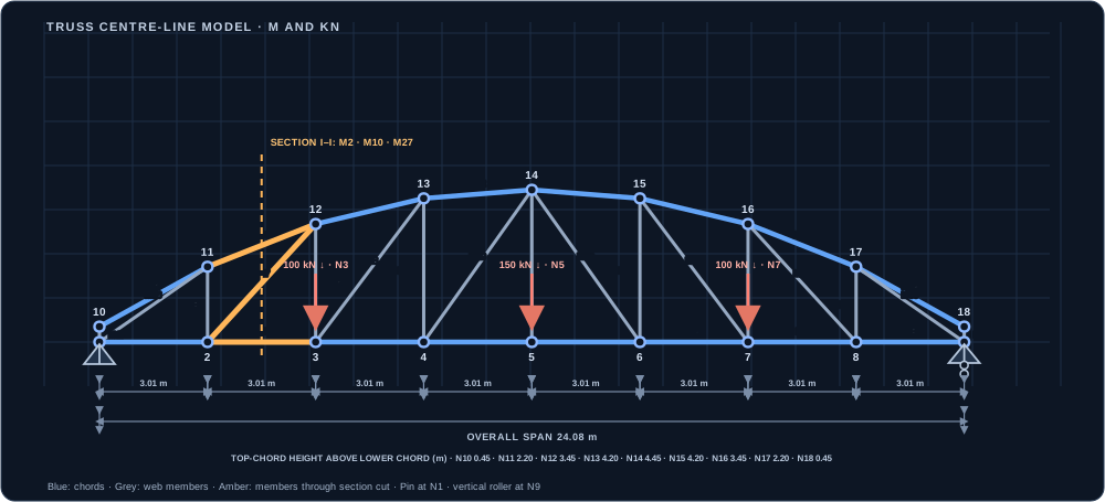
bridge-models/middle-road-truss.json. Amber members cross section I–I. Dimensions are in metres.Three vertical point loads act downward at lower-chord nodes 3, 5, and 7:
Total applied load = 350 kN. No horizontal loads or applied moments.
Taking moments about the left support and then summing vertical forces gives the reactions. There is no applied horizontal load, so the pin’s horizontal reaction is zero.
At node 1, M1 runs horizontally to node 2 and M26 runs to node 11. Unloaded joint 10 first gives M9 = M17 = 0. The known force at node 1 is its 175 kN upward reaction. M26 has direction cosines (0.807342, 0.590084). Taking tension as positive:
Repeating joint equilibrium across the determinate truss gives the axial force in every member. Positive values indicate tension (T); negative values indicate compression (C).
The calculation log below exposes the sequence instead of reporting only final member forces. For every joint it shows the already-known force resultant, the member force unknowns, each scalar equilibrium equation using the member direction cosines, and the solved tension-positive axial forces.
Tension is positive. Each row lists the known force resultant at that joint (external loads, support reaction, and previously solved bars). Direction cosines are resolved from the listed node coordinates. The two scalar equilibrium equations are then solved for the currently unknown bar forces. Rows follow a valid solve order; zero-force members at unloaded joints are identified first.
| Joint | Known resultant (Fx, Fy), kN | Unknown members | Equilibrium equations | Solved axial force(s) |
|---|---|---|---|---|
| N10 | (0.000, 0.000) | M9, M17 | ΣFx: +0.86451 N9 = 0.000 ΣFy: +0.50262 N9 -1.00000 N17 = 0.000 | N9 = 0.000 kN, N17 = 0.000 kN |
| N1 | (0.000, 175.000) | M1, M26 | ΣFx: +1.00000 N1 +0.80734 N26 = 0.000 ΣFy: +0.59008 N26 = -175.000 | N1 = 239.432 kN, N26 = -296.568 kN |
| N11 | (239.432, 175.000) | M10, M18 | ΣFx: +0.92353 N10 = -239.432 ΣFy: +0.38353 N10 -1.00000 N18 = -175.000 | N10 = -259.257 kN, N18 = 75.568 kN |
| N2 | (-239.432, 75.568) | M2, M27 | ΣFx: +1.00000 N2 +0.65742 N27 = 239.432 ΣFy: +0.75352 N27 = -75.568 | N2 = 305.362 kN, N27 = -100.286 kN |
| N12 | (305.362, 175.000) | M11, M19 | ΣFx: +0.97033 N11 = -305.362 ΣFy: +0.24178 N11 -1.00000 N19 = -175.000 | N11 = -314.699 kN, N19 = 98.913 kN |
| N3 | (-305.362, -1.087) | M3, M28 | ΣFx: +1.00000 N3 +0.58252 N28 = 305.362 ΣFy: +0.81282 N28 = 1.087 | N3 = 304.583 kN, N28 = 1.337 kN |
| N13 | (304.583, 75.000) | M12, M20 | ΣFx: +0.99657 N12 = -304.583 ΣFy: +0.08277 N12 -1.00000 N20 = -75.000 | N12 = -305.632 kN, N20 = 49.702 kN |
| N4 | (-304.583, 49.702) | M4, M29 | ΣFx: +1.00000 N4 +0.56027 N29 = 304.583 ΣFy: +0.82831 N29 = -49.702 | N4 = 338.202 kN, N29 = -60.005 kN |
| N5 | (-338.202, -150.000) | M5, M21 | ΣFx: +1.00000 N5 = 338.202 ΣFy: +1.00000 N21 = 150.000 | N5 = 338.202 kN, N21 = 150.000 kN |
| N14 | (338.202, -75.000) | M13, M30 | ΣFx: +0.99657 N13 +0.56027 N30 = -338.202 ΣFy: -0.08277 N13 -0.82831 N30 = 75.000 | N13 = -305.632 kN, N30 = -60.005 kN |
| N6 | (-304.583, -49.702) | M6, M22 | ΣFx: +1.00000 N6 = 304.583 ΣFy: +1.00000 N22 = 49.702 | N6 = 304.583 kN, N22 = 49.702 kN |
| N15 | (304.583, -75.000) | M14, M31 | ΣFx: +0.97033 N14 +0.58252 N31 = -304.583 ΣFy: -0.24178 N14 -0.81282 N31 = 75.000 | N14 = -314.699 kN, N31 = 1.337 kN |
| N7 | (-305.362, -98.913) | M7, M23 | ΣFx: +1.00000 N7 = 305.362 ΣFy: +1.00000 N23 = 98.913 | N7 = 305.362 kN, N23 = 98.913 kN |
| N16 | (305.362, -175.000) | M15, M32 | ΣFx: +0.92353 N15 +0.65742 N32 = -305.362 ΣFy: -0.38353 N15 -0.75352 N32 = 175.000 | N15 = -259.257 kN, N32 = -100.286 kN |
| N8 | (-239.432, -75.568) | M8, M24 | ΣFx: +1.00000 N8 = 239.432 ΣFy: +1.00000 N24 = 75.568 | N8 = 239.432 kN, N24 = 75.568 kN |
| N9 | (-239.432, 175.000) | M25, M33 | ΣFx: -0.80734 N33 = 239.432 ΣFy: +1.00000 N25 +0.59008 N33 = -175.000 | N25 = 0.000 kN, N33 = -296.568 kN |
| N17 | (0.000, 0.000) | M16 | ΣFx: +0.86451 N16 = 0.000 ΣFy: -0.50262 N16 = 0.000 | N16 = 0.000 kN |
| N18 | (0.000, 0.000) | None | All incident members are known; ΣFx = 0 and ΣFy = 0. | Equilibrium satisfied |
Section I–I cuts members M2, M10, and M27. Isolating the left-hand part and taking moments about node 1 eliminates the force in M2 because its line of action passes through that node. The three equilibrium equations are:
The section cut therefore gives M2 in tension and M10 and M27 in compression. No point load lies to the left of this cut, so these values are unchanged by moving the loads to nodes 3, 5, and 7.
For a truss, the displacement in a chosen direction follows from axial strain energy. Apply a unit downward force at the target node to obtain virtual member forces ni; combine them with actual member forces Ni:
For each target displacement, apply a unit downward force at that node and solve the virtual truss. With the three applied loads at N3, N5, and N7, the virtual-work results are 1.140831 mm downward at N3, 1.601666 mm downward at N5, and 1.140831 mm downward at N7.
| Result | Analytical method | FaxinaX static | Agreement |
|---|---|---|---|
| Reaction at node 1, R1y | 175.000 kN | 175.000 kN | Matches |
| Reaction at node 9, R9y | 175.000 kN | 175.000 kN | Matches |
| Member M1, N1 | +239.432 kN (T) | +239.432 kN (T) | Matches |
| Member M26, N26 | −296.568 kN (C) | −296.568 kN (C) | Matches |
| Member M2, N2 | +305.362 kN (T) | +305.362 kN (T) | Matches |
| Member M10, N10 | −259.257 kN (C) | −259.257 kN (C) | Matches |
| Member M27, N27 | −100.286 kN (C) | −100.286 kN (C) | Matches |
| Node 3 vertical deflection | −1.140831 mm | −1.140831 mm | Matches |
| Node 5 vertical deflection | −1.601666 mm | −1.601666 mm | Matches |
| Node 7 vertical deflection | −1.140831 mm | −1.140831 mm | Matches |
The independent joint-equilibrium solution was compared against the production api.analyze() solver for all 33 members. Maximum absolute axial-force difference: 1.14e-12 kN; maximum vertical reaction difference: 4.55e-13 kN. Virtual-work and FE displacements agree within numerical round-off at N3, N5, and N7.
| Member | Connectivity | Joints / sections (kN) | FE solver (kN) | State |
|---|---|---|---|---|
| M1 | 1–2 | 239.432 | 239.432 | Tension |
| M2 | 2–3 | 305.362 | 305.362 | Tension |
| M3 | 3–4 | 304.583 | 304.583 | Tension |
| M4 | 4–5 | 338.202 | 338.202 | Tension |
| M5 | 5–6 | 338.202 | 338.202 | Tension |
| M6 | 6–7 | 304.583 | 304.583 | Tension |
| M7 | 7–8 | 305.362 | 305.362 | Tension |
| M8 | 8–9 | 239.432 | 239.432 | Tension |
| M9 | 10–11 | 0.000 | 0.000 | Zero-force |
| M10 | 11–12 | −259.257 | −259.257 | Compression |
| M11 | 12–13 | −314.699 | −314.699 | Compression |
| M12 | 13–14 | −305.632 | −305.632 | Compression |
| M13 | 14–15 | −305.632 | −305.632 | Compression |
| M14 | 15–16 | −314.699 | −314.699 | Compression |
| M15 | 16–17 | −259.257 | −259.257 | Compression |
| M16 | 17–18 | 0.000 | 0.000 | Zero-force |
| M17 | 1–10 | 0.000 | 0.000 | Zero-force |
| M18 | 2–11 | 75.568 | 75.568 | Tension |
| M19 | 3–12 | +98.913 | +98.913 | Tension |
| M20 | 4–13 | 49.702 | 49.702 | Tension |
| M21 | 5–14 | +150.000 | +150.000 | Tension |
| M22 | 6–15 | 49.702 | 49.702 | Tension |
| M23 | 7–16 | +98.913 | +98.913 | Tension |
| M24 | 8–17 | 75.568 | 75.568 | Tension |
| M25 | 9–18 | 0.000 | 0.000 | Zero-force |
| M26 | 1–11 | −296.568 | −296.568 | Compression |
| M27 | 2–12 | −100.286 | −100.286 | Compression |
| M28 | 3–13 | 1.337 | 1.337 | Tension |
| M29 | 4–14 | −60.005 | −60.005 | Compression |
| M30 | 6–14 | −60.005 | −60.005 | Compression |
| M31 | 7–15 | 1.337 | 1.337 | Tension |
| M32 | 8–16 | −100.286 | −100.286 | Compression |
| M33 | 9–17 | −296.568 | −296.568 | Compression |
This case follows the complete route a user takes: analyse a portal frame under horizontal and vertical load, take the column forces to the EN 1993-1-1 member check, and compare every step with an independent calculation or with a published result. The frame is the simplest one that still contains sway, fixed-base moments, axial force, double-curvature bending, flexural buckling and lateral-torsional buckling in the same column.
Strong-axis bending acts in the frame plane. Buckling lengths entered for the check: Lcr,y = 1.5h = 6.00 m (sway frame, an engineering choice discussed below), and Lcr,z = Lcr,T = Lcr,LT = 4.00 m (column restrained against out-of-plane movement at base and beam level).
For a fixed-base portal frame with all three members of equal EI and length L, loaded by a horizontal force P at beam level, a published closed-form solution gives sway 5PL3/(84EI), column base moments 2PL/7 and column top moments 3PL/14 (Wolfram Cloud notebook, portal frame with fixed column bases and top horizontal load). The same case was run in FaxinaX with HEB 200 members, L = 4 m and P = 50 kN. Axial deformation was suppressed with a very large area so that the solver matches the classical assumption of axially rigid members.
| Quantity | Published formula | Published value | FaxinaX | Relative error | Status |
|---|---|---|---|---|---|
| Sway of beam level | 5PL³/(84EI) | 15.9240 mm | 15.9240 mm | 3.7e-06 % | PASS |
| Base moment, left column | 2PL/7 | 57.1429 kNm | 57.1429 kNm | 2.2e-06 % | PASS |
| Base moment, right column | 2PL/7 | 57.1429 kNm | 57.1429 kNm | 2.8e-07 % | PASS |
| Top moment, left column | 3PL/14 | 42.8571 kNm | 42.8571 kNm | 3.4e-07 % | PASS |
| Base horizontal reaction, each column | P/2 | 25.0000 kN | 25.0000 kN | 1.1e-06 % | PASS |
The published case has equal members. The general case, with a different column and beam, was checked next against the slope-deflection method written independently of the solver. For the sway case the joint rotation θ and the storey sway Δ follow from the joint-moment equation MBA + MBC = 0 and the column shear condition 2(MAB + MBA)/h = H, with MAB = (2EIc/h)(θ − 3Δ/h), MBA = (2EIc/h)(2θ − 3Δ/h) and MBC = 6EIbθ/L. For the vertical load the frame does not sway and θ = (wL2/12)/(4EIc/h + 2EIb/L). The two load cases are verified separately because the combined result is their sum.
| Quantity | Method | Hand calculation | FaxinaX | Relative error | Status |
|---|---|---|---|---|---|
| Horizontal load H · sway | slope-deflection | 34.6976 mm | 34.6976 mm | 2.5e-06 % | PASS |
| Horizontal load H · column base moment | slope-deflection | 88.2265 kNm | 88.2265 kNm | 1.8e-06 % | PASS |
| Horizontal load H · column top moment | slope-deflection | 71.7735 kNm | 71.7735 kNm | 6.8e-07 % | PASS |
| Horizontal load H · column axial force (±) | moment equilibrium of the whole frame | 23.9245 kN | 23.9245 kN | 3.3e-07 % | PASS |
| Vertical load w · column base moment | slope-deflection | 34.7413 kNm | 34.7413 kNm | 2.3e-06 % | PASS |
| Vertical load w · column top moment | slope-deflection | 69.4826 kNm | 69.4826 kNm | 6.8e-07 % | PASS |
| Vertical load w · horizontal thrust at each base | equilibrium of column | 26.0560 kN | 26.0560 kN | 1.2e-06 % | PASS |
| Vertical load w · column axial force | wL/2 | 120.0000 kN | 120.0000 kN | 0.0e+00 % | PASS |
The combined factored load case was analysed with the real section properties. The right-hand column carries the larger actions. The design check takes the maximum compression, the maximum bending moment and the maximum shear from the member's result stations, exactly as the Design tab does for a selected member.
| Action on right-hand column | Value |
|---|---|
| Compression NEd | 143.91 kN |
| Maximum moment My,Ed (at beam joint) | 140.99 kNm |
| Moment at base | 122.63 kNm, opposite curvature |
| End-moment ratio ψ | -0.870 |
| Maximum shear Vz,Ed | 65.91 kN |
An independent evaluation of the same checks was written directly from the clauses of EN 1993-1-1 (6.2.5, 6.2.6, 6.2.9, 6.3.1, 6.3.2.2, 6.3.3 and Annex B Tables B.1 and B.3), using only the section dimensions and the cross-section constants of the table. The elastic critical moment is taken from the standard closed form Mcr = C1(π2EIz/L2)√(Iw/Iz + L2GIt/(π2EIz)) with C1 = 2.581 for ψ = -0.870 (tabulated end-moment values, linearly interpolated). FaxinaX obtains Mcr from its own LTB tables, so to isolate the code-check arithmetic the comparison below enters the independent Mcr = 736.3 kNm directly. The table-based Mcr is compared afterwards.
| Quantity | FaxinaX | Independent | Difference | Status |
|---|---|---|---|---|
| Section class (1 = plastic) | 1 | 1 | 0.00 % | PASS |
| Plastic axial resistance Npl,Rd | 2316.4 kN | 2316.4 kN | 0.00 % | PASS |
| Moment resistance MN,y,Rd | 170.94 kNm | 170.94 kNm | 0.00 % | PASS |
| Shear resistance Vpl,z,Rd | 414.8 kN | 414.8 kN | 0.00 % | PASS |
| Slenderness λ̄y (Lcr = 6 m) | 1.0251 | 1.0248 | 0.03 % | PASS |
| Reduction χy (curve b) | 0.5812 | 0.5814 | 0.03 % | PASS |
| Slenderness λ̄z (Lcr = 4 m) | 1.1455 | 1.1454 | 0.01 % | PASS |
| Reduction χz (curve c) | 0.4606 | 0.4607 | 0.01 % | PASS |
| Buckling resistance Nb,y,Rd | 1346.2 kN | 1346.7 kN | 0.03 % | PASS |
| Buckling resistance Nb,z,Rd | 1066.9 kN | 1067.0 kN | 0.01 % | PASS |
| λ̄LT (with Mcr entered) | 0.4818 | 0.4818 | 0.00 % | PASS |
| χLT (curve a) | 0.9298 | 0.9298 | 0.00 % | PASS |
| Mb,Rd | 158.95 kNm | 158.95 kNm | 0.00 % | PASS |
| Equivalent moment factor Cmy = Cm,LT | 0.400 | 0.400 | 0.00 % | PASS |
| Interaction factor kyy | 0.4342 | 0.4342 | 0.00 % | PASS |
| Interaction factor kzy | 0.9101 | 0.9101 | 0.00 % | PASS |
| Check | FaxinaX | Independent | Absolute difference | Status |
|---|---|---|---|---|
| Axial cross-section | 0.0621 | 0.0621 | 0.0000 | PASS |
| Bending y-axis | 0.8248 | 0.8248 | 0.0000 | PASS |
| Shear z-direction | 0.1589 | 0.1589 | 0.0000 | PASS |
| Flexural buckling y-axis | 0.1069 | 0.1069 | 0.0000 | PASS |
| Flexural buckling z-axis | 0.1349 | 0.1349 | 0.0000 | PASS |
| Lateral torsional buckling | 0.8870 | 0.8870 | 0.0000 | PASS |
| Interaction EN 1993-1-1 (6.61) | 0.4921 | 0.4920 | 0.0000 | PASS |
| Interaction EN 1993-1-1 (6.62) | 0.9422 | 0.9422 | 0.0000 | PASS |
The same member-check functions were evaluated with the inputs of a published worked example for a UKC 254×254×89 column in S275 (fy = 265 N/mm², 3.5 m buckling length, NEd = 1500 kN, My,Ed = 89 kNm, Mz,Ed = 7.9 kNm, Cmy = Cmz = 0.9, Cm,LT = 0.946), as printed by Structville, Design of Steel Columns for Biaxial Bending. Section constants were taken from the example's own printed values.
| Quantity | Published | FaxinaX | Difference | Status |
|---|---|---|---|---|
| λ̄y | 0.353 | 0.353 | 0.09 % | PASS |
| λ̄z | 0.604 | 0.604 | 0.08 % | PASS |
| χy | 0.944 | 0.944 | 0.05 % | PASS |
| χz | 0.783 | 0.783 | 0.03 % | PASS |
| Nb,y,Rd (kN) | 2835.9 | 2836.2 | 0.01 % | PASS |
| Nb,z,Rd (kN) | 2350.4 | 2350.5 | 0.01 % | PASS |
| kyy | 0.973 | 0.973 | 0.03 % | PASS |
| kyz | 0.750 | 0.750 | 0.02 % | PASS |
| kzy | 0.945 | 0.945 | 0.04 % | PASS |
| kzz | 1.250 | 1.250 | 0.02 % | PASS |
Every intermediate value agrees with the published example to its printed precision (differences ≤ 0.1 %). Combining the printed intermediate values gives utilisations 0.835 for (6.61) and 0.962 for (6.62); the article prints 0.838 and 0.965. That is a gap of about 0.003 in both checks, which cannot be traced from the numbers printed in the article, so the agreement band for the combined ratio is taken as ±0.5 %.
The 3D workspace uses a separate solver: 12-degree-of-freedom Timoshenko beam elements, six degrees of freedom per node, exact fixed-end loads, end releases by static condensation, and a single sparse factorisation for all load cases. Modal analysis solves Kφ = ω²Mφ with consistent (or lumped) mass; response spectrum analysis combines the modal peaks by CQC or SRSS. The steel check passes the 3D member forces to the same EN 1993-1-1 engine as the 2D workspace. The cases below are closed-form or independent hand solutions, and are also run as automated tests (tests/test_space_frame.py and tests/test_space_design.py).
Timoshenko cantilever, L = 4 m, E = 210 GPa, G = 81 GPa, Iy = 8×10⁻⁵ m⁴, Av,z = 0.005 m², P = 20 kN. Exact tip deflection δ = PL³/(3EI) + PL/(GAv).
| Quantity | Closed form | FaxinaX 3D | Relative error | Status |
|---|---|---|---|---|
| tip deflection | 25.5944 mm | 25.5944 mm | 1.39e-14 % | PASS |
| fixed-end moment | 80.0000 kNm | 80.0000 kNm | 1.78e-14 % | PASS |
Saint-Venant torsion, T = 5 kNm, J = 3×10⁻⁵ m⁴: φ = TL/(GJ).
| Quantity | Closed form | FaxinaX 3D | Relative error | Status |
|---|---|---|---|---|
| end twist | 0.008230 rad | 0.008230 rad | 0.00e+00 % | PASS |
Four elements, q = 15 kN/m downward, L = 4 m, Euler–Bernoulli option: M = qL²/12 and δmid = qL⁴/(384EI).
| Quantity | Closed form | FaxinaX 3D | Relative error | Status |
|---|---|---|---|---|
| end moment | 20.0000 kNm | 20.0000 kNm | 3.55e-14 % | PASS |
| midspan deflection | 0.5952 mm | 0.5952 mm | 7.46e-14 % | PASS |
One member, fixed at one end, moment release and vertical support at the other end, q = 15 kN/m: R = 3qL/8, Mfixed = qL²/8.
| Quantity | Closed form | FaxinaX 3D | Relative error | Status |
|---|---|---|---|---|
| prop reaction 3qL/8 | 22.5000 kN | 22.5000 kN | 0.00e+00 % | PASS |
| fixed-end moment qL²/8 | 30.0000 kNm | 30.0000 kNm | 0.00e+00 % | PASS |
Three axial-only bars (apex at 3 m height, base circle radius 2 m), P = 60 kN: N = P/(3 cos θ) and δz = N L/(EA cos θ), θ measured from the vertical.
| Quantity | Closed form | FaxinaX 3D | Relative error | Status |
|---|---|---|---|---|
| bar axial force | -24.0370 kN | -24.0370 kN | 0.00e+00 % | PASS |
| apex deflection N·L/(EA cosθ) | 0.2480 mm | 0.2480 mm | 0.00e+00 % | PASS |
L = 5 m, A = 0.01 m², I = 8×10⁻⁵ m⁴, ρ = 7850 kg/m³, consistent mass matrix. Exact frequencies fn = (βnL)²/(2πL²)·√(EI/ρA), β1L = 1.8751, β2L = 4.6941. The finite-element value converges from above as the mesh is refined.
| Quantity | Closed form | FaxinaX 3D | Relative error | Status |
|---|---|---|---|---|
| first bending frequency | 10.3550 Hz | 10.3550 Hz | 2.08e-04 % | PASS |
| second bending frequency | 64.8938 Hz | 64.8990 Hz | 8.00e-03 % | PASS |
Same beam, pinned at one end and on a roller at the other: f1 = (π/2L²)·√(EI/ρA).
| Quantity | Closed form | FaxinaX 3D | Relative error | Status |
|---|---|---|---|---|
| first bending frequency | 29.0670 Hz | 29.0674 Hz | 1.64e-03 % | PASS |
Single degree of freedom: m = 1000 kg from a load case (W/g), f = (1/2π)·√(3EI/(mL³)).
| Quantity | Closed form | FaxinaX 3D | Relative error | Status |
|---|---|---|---|---|
| natural frequency | 4.4663 Hz | 4.4663 Hz | 0.00e+00 % | PASS |
One-mode system with a flat spectrum: base shear = m Sa, base moment = m Sa L, peak displacement = Sa/ω².
| Quantity | Closed form | FaxinaX 3D | Relative error | Status |
|---|---|---|---|---|
| base shear m·S_a | 3.0000 kN | 3.0000 kN | 5.92e-14 % | PASS |
| base moment m·S_a·L | 12.0000 kNm | 12.0000 kNm | 4.44e-14 % | PASS |
| peak tip displacement S_a/ω² | 3.8095 mm | 3.8095 mm | 4.66e-14 % | PASS |
Simply supported span, My,Ed = qL²/8 = 90 kNm, Wpl,y from the section database.
| Quantity | Closed form | FaxinaX 3D | Relative error | Status |
|---|---|---|---|---|
| bending ratio M_Ed/(W_pl,y f_y) | 0.13564 | 0.13564 | 2.05e-14 % | PASS |
Pure compression, weak-axis flexural buckling, curve c (α = 0.49): λ̄ = Lcr/(izπ√(E/fy)), χ = 1/(Φ+√(Φ²−λ̄²)).
| Quantity | Closed form | FaxinaX 3D | Relative error | Status |
|---|---|---|---|---|
| weak-axis buckling ratio N/(χ A f_y), curve c | 0.11342 | 0.11342 | 0.00e+00 % | PASS |
The same test suite also checks: pin-ended uniform load and its midspan deflection, point-load shear jumps, self-weight, local-axis conventions for vertical and inclined members and roll angles, rotation invariance of an isotropic frame, a portal frame against an independent 2D Euler solution, load combinations, rejection of unstable models, sparse-versus-dense eigen solvers, mode participation of a cantilever (61.3 % per direction in the first bending mode), axial and torsional modes, direction combination and the displacement scale factor. Steel checks use the envelope of N, Vy, Vz, T, My and Mz along the member (not simultaneous), which is conservative. Response spectrum results are envelope amplitudes, not simultaneous values. These are idealised benchmark checks, not proof that every possible model is error-free.
Cladding panels (one-way or two-way) turn a surface pressure into trapezoidal member loads; the 3D solver integrates them exactly (Gauss quadrature of the point-load fixed-end terms, closed-form shear and moment along the member). Wind pressures come from the EN 1991-1-4 generator, which reproduces the reference spreadsheet calculator (qp = 0.857 kN/m², walls A −1.03, B −0.69, C −0.43, D +0.59, E −0.37 kN/m²). The cases below are also run as automated tests (tests/test_space_frame.py, tests/test_cladding_engine.py and tests/test_wind_engine.py).
Arm 1 along X (a = 4 m) fixed at the origin, arm 2 along Y (b = 3 m) loaded by P = 8 kN at its tip, Euler option. The tip deflection is P a³/3EI + P b³/3EI + P b² a/GJ; the last term exists only if the torsional degree of freedom (RX) of the joint works.
| Quantity | Reference | FaxinaX 3D | Relative error | Status |
|---|---|---|---|---|
| tip deflection | 370.0000 mm | 370.0000 mm | 8.14e-13 % | PASS |
| root torque | 24.0000 kNm | 24.0000 kNm | 8.14e-13 % | PASS |
| root bending moment | 32.0000 kNm | 32.0000 kNm | 1.18e-12 % | PASS |
Load rising from 0 to w = 12 kN/m over L = 6 m (a trapezoidal member load). RA = wL/6, RB = wL/3, M(L/2) = wL²/16.
| Quantity | Reference | FaxinaX 3D | Relative error | Status |
|---|---|---|---|---|
| reaction at the zero end (wL/6) | 12.0000 kN | 12.0000 kN | 4.44e-14 % | PASS |
| reaction at the loaded end (wL/3) | 24.0000 kN | 24.0000 kN | 0.00e+00 % | PASS |
| moment at midspan (wL²/16) | 27.0000 kNm | 27.0000 kNm | 5.26e-14 % | PASS |
L = 6 m, w = 9 kN/m, Euler option; closed-form tip deflections of the two triangular patterns.
| Quantity | Reference | FaxinaX 3D | Relative error | Status |
|---|---|---|---|---|
| tip deflection, peak at the root (wL⁴/30EI) | 23.1429 mm | 23.1429 mm | 9.21e-14 % | PASS |
| tip deflection, peak at the tip (11wL⁴/120EI) | 63.6429 mm | 63.6429 mm | 4.47e-14 % | PASS |
The 45° tributary loads of a panel lx × ly on a simply supported edge beam give the midspan moment weq L²/8 with weq = p lx/3 (triangular, short edge) and (p lx/2)(1 − 1/(3k²)), k = ly/lx (trapezoidal, long edge) — the classical slab-to-beam distribution.
| Quantity | Reference | FaxinaX 3D | Relative error | Status |
|---|---|---|---|---|
| long edge, 4 × 6 m panel, p = 3 kN/m² (weq = (p lx/2)(1 − 1/3k²)) | 23.0000 kNm | 23.0000 kNm | 0.00e+00 % | PASS |
| long edge, 4 × 8 m panel, p = 3 kN/m² (weq = (p lx/2)(1 − 1/3k²)) | 44.0000 kNm | 44.0000 kNm | 3.23e-14 % | PASS |
| long edge, 5 × 5 m panel, p = 3 kN/m² (weq = (p lx/2)(1 − 1/3k²)) | 15.6250 kNm | 15.6250 kNm | 4.55e-14 % | PASS |
| short edge, 4 × 6 m panel, p = 3 kN/m² (weq = p lx/3) | 8.0000 kNm | 8.0000 kNm | 0.00e+00 % | PASS |
| short edge, 4 × 8 m panel, p = 3 kN/m² (weq = p lx/3) | 8.0000 kNm | 8.0000 kNm | 0.00e+00 % | PASS |
Roof panel 12 × 8 m on a box frame, p = 2.5 kN/m², two-way, edges made of member chains. The support reactions must carry the panel load exactly.
| Quantity | Reference | FaxinaX 3D | Relative error | Status |
|---|---|---|---|---|
| Σ vertical reactions (p·A = 2.5 × 96) | 240.0000 kN | 240.0000 kN | 2.37e-14 % | PASS |
Three portal frames at 5 m, span 10 m, eaves 5 m, 10° roof, cladding panels on walls and roof; vb,0 = 23 m/s, terrain II, wind along the ridge, cpi = +0.2, zone at the panel centre. Base shear along the ridge equals (we,D − we,E) × end-wall area; vertical reactions equal the sum of p·A·nz over the panels.
| Quantity | Reference | FaxinaX 3D | Relative error | Status |
|---|---|---|---|---|
| qp(ze = h) (kN/m²) | 0.6696 kN/m² | 0.6696 kN/m² | 0.00e+00 % | PASS |
| base shear along the ridge, (we,D − we,E)·A end wall | 32.3082 kN | 32.3082 kN | 5.08e-12 % | PASS |
| Σ vertical reactions = Σ p·A·nz of all panels | 53.5693 kN | 53.5693 kN | 6.63e-14 % | PASS |
Also tested: one-way and two-way edge loads and their totals (p·A), square panels (four triangles), a chain of several members along one panel edge, members drawn in the opposite direction to the edge, reporting of load that has no member underneath, rejection of non-rectangular panels, detection of rectangular faces from the members (a rail across a face splits it), the roof and wall zone assignment for four wind directions, the cancellation of internal pressure in the horizontal force, and the solver reactions of the generated wind cases against the applied resultant. Limits: rectangular panels only; one qp(ze) for the whole building; pressures use the loaded area of each zone (frame-level), so the local cpe,1 of fixings and sheeting needs a separate check. These are idealised benchmark checks, not proof that every possible model is error-free.
The 3D workspace is a 3D Structure: beams and four-node shell elements (walls, slabs, plates) share the same nodes, with six degrees of freedom at every node (ux, uy, uz, θx, θy, θz). One global stiffness matrix is assembled from the beam matrices and the shell matrices and solved once for all load cases.
Results are the membrane forces nx, ny, nxy (kN/m), the bending and twisting moments mx, my, mxy (kNm/m) and the transverse shears qx, qy (kN/m), at the centre and the four corners, plus the von Mises stress on the top and bottom surfaces. The contour on the canvas averages the corner values at shared nodes. Pressure loads and self-weight are lumped consistently to the nodes; gravity, wind and user pressures are all area loads.
Checks run: six rigid-body modes and no spurious zero-energy mode; membrane and bending patch tests; simply supported and clamped square plates; Scordelis–Lo roof (vertical displacement of the free edge 0.301 against the reference 0.3024); beam and shell cantilevers; coupling of a beam into a shell edge; self-weight and combinations; free vibration of a simply supported plate (first frequency within 1 % of the closed form). They are automated in tests/test_shell_solver.py.
Cracking lowers the stiffness of reinforced concrete members, so a linear analysis of a concrete structure multiplies the gross-section stiffness by modifiers. In FaxinaX each modifier belongs to one stiffness term, that is, to one degree of freedom of the element, and is entered between 0.001 and 10 (default 1.0).
| Element | Modifier | Stiffness it multiplies | Degree of freedom |
|---|---|---|---|
| Beam | A | EA | ux (axial) |
| Avy, Avz | GAvy, GAvz | uy, uz (shear) | |
| J | GJ | θx (torsion) | |
| Iy | EIy | θy (bending, deflection uz) | |
| Iz | EIz | θz (bending, deflection uy) | |
| Mass and self-weight keep the gross section. | |||
| Shell | f11, f22, f12 | Membrane stiffness in local x, local y and in-plane shear | u, v |
| m11, m22, m12 | Bending in x, bending in y and twisting | θx, θy (with w) | |
| v13, v23 | Transverse shear in the x–z and y–z planes | w | |
| Drilling penalty, mass and self-weight keep the gross values. | |||
The coupling term uses √(f11f22), so the modified matrix stays positive definite. Member forces and shell resultants are recovered with the modified stiffness, which keeps equilibrium exact.
| Preset in the program | Modifiers | Source |
|---|---|---|
| Beam | I = 0.35 | ACI 318-19 Table 6.6.3.1.1(a) |
| Column | I = 0.70 | ACI 318-19 Table 6.6.3.1.1(a) |
| Wall, uncracked / cracked | I = 0.70 / 0.35 (shell in-plane f = 0.70 / 0.35, bending m = 0.25 by common practice) | ACI 318-19 Table 6.6.3.1.1(a) |
| Flat plate or slab | bending m = 0.25 | ACI 318-19 Table 6.6.3.1.1(a) |
| Cracked element, flexure and shear | 0.5 | EN 1998-1 4.3.1(7): half of the uncracked flexural and shear stiffness |
The presets are starting values taken from the published tables; they are editable and are not a design recommendation. Use values appropriate to the load level (service or ultimate), to your national annex, and to the reinforcement. A modifier of 0.35 on I increases a flexural deflection by 1/0.35 = 2.86 at the same load. The test suite checks that A, Iy and J change only their own degree of freedom in the beam, for the shell bending (ratio 3.96 for m = 0.25, just under 4 because shear deformation is not reduced) and for the membrane (f11 = 0.5 doubles the in-plane extension).
This section writes out how the beam and shell elements of the 3D workspace are formulated, how they are joined into one structure, and how forces are recovered. The formulations are the standard ones of the finite element literature listed under References; the numbers in square brackets point to that list.
Every node has six degrees of freedom, \(\mathbf d_i=[u,v,w,\theta_x,\theta_y,\theta_z]^T\) in global axes. Beams and shells use the same six, so they are joined simply by sharing a node: translations and all three rotations are continuous there. Each element matrix is built in its own local axes, rotated to global axes, and added at the positions of its nodes:
\(\mathbf A_e\) is the Boolean connectivity matrix of the element. \(\mathbf T_e\) is block diagonal with the 3×3 rotation \(\mathbf R=[\mathbf e_x\ \mathbf e_y\ \mathbf e_z]^T\) of the element local axes, repeated for the translation and rotation parts of every node (12×12 for a beam, 24×24 for a four-node shell, 18×18 for a triangle). Restrained degrees of freedom are removed, the free system is solved with a sparse direct solver, and the reactions are \(\mathbf R_s=\mathbf K_{sf}\mathbf d_f-\mathbf F_s\) [1,2,3].
Axial and torsional behaviour are linear bars; bending in each principal plane is a Timoshenko beam, which keeps the shear deformation that the Euler–Bernoulli element neglects [4,5,6]. With the shear parameter \(\Phi=\dfrac{12EI}{GA_v L^2}\) the bending block of one plane, for deflection \(v\) and rotation \(\theta\), is
It is used once with \((I_z,A_{vy})\) for bending in the x–y plane and once with \((I_y,A_{vz})\) for the x–z plane, and \(\Phi=0\) gives the Euler–Bernoulli matrix. The local axes are \(\mathbf e_x\) along the member, \(\mathbf e_z\) upward (or global X for vertical members) and \(\mathbf e_y=\mathbf e_z\times\mathbf e_x\), then rotated by the roll angle. A release (hinge) at an end is applied by static condensation of that degree of freedom, \(\mathbf k'=\mathbf k_{aa}-\mathbf k_{ab}\mathbf k_{bb}^{-1}\mathbf k_{ba}\), so the member end carries no force in it [3,6]. Stiffness modifiers multiply the individual terms \(EA,\ GA_v,\ GJ,\ EI_y,\ EI_z\).
Complete element stiffness matrix. Joining the axial bar, the torsion bar and the two bending blocks gives the 12×12 local stiffness matrix of the Timoshenko beam element. The degrees of freedom of the two ends are ordered \(\mathbf d^{\ell}=[u_1,v_1,w_1,\theta_{x1},\theta_{y1},\theta_{z1},\;u_2,v_2,w_2,\theta_{x2},\theta_{y2},\theta_{z2}]^T\) in the local axes, with \(\mathbf f^{\ell}=\mathbf k^{\ell}\mathbf d^{\ell}\).
The matrix is symmetric and has exactly six zero eigenvalues, the six rigid-body motions. Bending in the x–z plane uses the same block as the x–y plane with the signs of the \(w\)–\(\theta_y\) coupling terms reversed, because the rotation about the local y axis is \(\theta_y=-\mathrm dw/\mathrm dx\). The entries above are the ones the solver assembles: they were compared numerically with the matrix produced by the program for a test member and agree to rounding error. Setting \(\Phi_y=\Phi_z=0\) gives the Euler–Bernoulli matrix, and the stiffness modifiers scale \(EA\), \(GJ\), \(EI_y\), \(EI_z\) and the shear areas before the matrix is formed.
Member loads become consistent nodal loads, for example a uniform load \(q\) gives \(\mathbf f=[\tfrac{qL}{2},\ \tfrac{qL^2}{12},\ \tfrac{qL}{2},\ -\tfrac{qL^2}{12}]^T\) per bending plane, and a point load \(P\) at \(a\) gives the usual fixed-end forces. Warping torsion of open sections is not part of the 12-degree-of-freedom element; it is recovered afterwards from the torque (see the warping post-processing in the steel check) with Vlasov's theory [7].
The shell is flat. In the local frame \(\mathbf e_x,\mathbf e_y,\mathbf e_z\) (normal \(\mathbf e_z=\mathbf d_1\times\mathbf d_2\), the cross product of the diagonals) its 24 degrees of freedom split into membrane \((u,v)\), plate \((w,\theta_x,\theta_y)\) and drilling \((\theta_z)\) parts, with the isoparametric map \(\mathbf x=\sum_i N_i(\xi,\eta)\mathbf x_i\), \(N_i=\tfrac14(1+\xi_i\xi)(1+\eta_i\eta)\) and Jacobian \(\mathbf J=\partial\mathbf x/\partial(\xi,\eta)\) [1,2,3]. The element matrix is
Membrane. The displacement field is enriched with incompatible modes, \(\mathbf u=\sum N_i\mathbf u_i+\sum_{k=1}^{2}M_k\boldsymbol\alpha_k\) with \(M_1=1-\xi^2\) and \(M_2=1-\eta^2\) (four extra parameters, two per direction) [8,9]. The enhanced strain–displacement matrix is evaluated with the Taylor correction \(\mathbf B_\alpha=\dfrac{\det\mathbf J_0}{\det\mathbf J}\mathbf J_0^{-T}\nabla_{\xi\eta}M\), where \(\mathbf J_0\) is the Jacobian at the element centre, which makes the element pass the patch test on distorted meshes [9]. The parameters \(\boldsymbol\alpha\) are condensed out at element level:
Plate bending and shear. With the Reissner–Mindlin kinematics [10,11] the curvatures are \(\boldsymbol\kappa=[\partial\theta_y/\partial x,\ -\partial\theta_x/\partial y,\ \partial\theta_y/\partial y-\partial\theta_x/\partial x]^T\) and the transverse shear strains \(\boldsymbol\gamma=\nabla w-\boldsymbol\theta\). Evaluated directly at the Gauss points, the shear strains lock when the plate is thin. The MITC4 element [12,13] replaces them by an interpolation of the covariant strains sampled at four tying points at the mid-sides:
which are then transformed to the local Cartesian components with \(\mathbf J^{-1}\). The shear correction factor is \(\kappa=5/6\). Integration is 2×2 Gauss for all terms. The constitutive matrices are \(\mathbf D_m=\dfrac{Et}{1-\nu^2}\begin{bmatrix}1&\nu&0\\\nu&1&0\\0&0&\frac{1-\nu}{2}\end{bmatrix}\) and \(\mathbf D_b=\dfrac{t^2}{12}\mathbf D_m\).
Drilling rotation. A flat shell has no stiffness for \(\theta_z\), so a beam or another shell meeting it in a different plane would give a singular matrix. The rotation is tied to the in-plane rotation of the continuum by a penalty on \(\theta_z-\omega\), \(\omega=\tfrac12(\partial v/\partial x-\partial u/\partial y)\), with a small coefficient \(\gamma\); \(\mathbf b_d\) is the row that evaluates it. This is the penalty form of the variational formulation of Hughes and Brezzi [14], whose behaviour in membrane elements was assessed by Hughes, Masud and Harari [31] and which Ibrahimbegović, Taylor and Wilson [32] used for a quadrilateral; the older alternative is Allman's special displacement interpolation with vertex rotations [30]. In that literature the penalty parameter is a free parameter, reported of the order of the shear modulus or a fraction of it. FaxinaX uses the much smaller \(\gamma=10^{-4}\) (times \(Gt\)) because \(\theta_z\) mainly has to be non-singular where a beam or a second shell is attached, not to reproduce an accurate in-plane rotation field. The value is the program's own choice and is not taken from the references; it is small enough not to stiffen the membrane and large enough to keep the system well conditioned.
The triangle keeps the same split. The membrane and drilling parts are built from three QM6 sub-quadrilaterals formed with the corners, the side mid-points and the centroid; the mid-side degrees of freedom follow the corners linearly and the centroid is condensed out, so neighbouring shells remain conforming. The plate part is a Reissner–Mindlin triangle with linear \(w,\theta_x,\theta_y\) and MITC3-type shear strains tied to the tangential shear strain at the three side mid-points [15], which is free of shear locking and passes the constant-curvature patch test.
A pressure \(p\) (gravity, wind, user pressure) is converted to consistent nodal forces \(\mathbf f=\int_A\mathbf N^Tp\,\mathbf n\,dA\) on the translations, and the self-weight is \(\rho g t\) over the area. The wind loads of EN 1991-1-4 act on the shells through the same area-load vector, so they appear in the combinations exactly like any other pressure.
| Test | What it shows | Reference problem |
|---|---|---|
| Rigid-body modes | six zero eigenvalues and no spurious zero-energy mode of the shell matrix | [1,2] |
| Patch tests | constant membrane stress and constant curvature are reproduced on distorted meshes | [9,16] |
| Simply supported and clamped square plate | centre deflection within 1 % of the thin-plate series | [17] |
| Scordelis–Lo roof | vertical displacement of the free edge 0.301 against 0.3024 | [18,16] |
| Beam into shell edge | load carried through the shared nodes, reactions in equilibrium | this program |
| Triangle shell and disc meshes | rotation and node-order invariance; clamped disc centre deflection \(qa^4/64D\) | [15,17] |
The tests are automated in tests/test_shell_solver.py. They validate the formulation on the standard benchmarks; a project model still needs its own review of supports, mesh density and the position of the beam relative to the shell mid-surface.
Verification: tests/test_wind_engine.py, tests/test_wind_fig74.py and tests/test_cladding_engine.py check the zone tables, qp by hand, force equilibrium of the generated cases and the resultant of the shell pressures. The generated wind loads should still be reviewed against the building and the national annex.
A solver always returns numbers. Whether they are believable is an engineering judgement, and it is best made before looking at the values: sketch the load path, the deflected shape and the bending moment diagram you expect, then compare. Most serious errors are visible at that level.
Use these relations to read a diagram quickly. Uniform load gives linear shear and parabolic moment, a point load gives constant shear segments and linear moment, and a member with no load between its ends has linear moment. If a diagram shows a curve where there is no load, or a jump where nothing is applied, the model is not what you meant.
Compare the order of magnitude with the closed-form values below (prismatic member, length L, flexural rigidity EI, uniform load q, point load P). The first benchmark cases on this page use the same formulas.
| Case | Maximum moment | Maximum deflection |
|---|---|---|
| Simply supported, uniform load | qL²/8 at midspan | 5qL⁴/(384EI) |
| Simply supported, midspan point load | PL/4 at midspan | PL³/(48EI) |
| Fixed at both ends, uniform load | qL²/12 at the ends (hogging), qL²/24 at midspan | qL⁴/(384EI) |
| Cantilever, uniform load | qL²/2 at the support | qL⁴/(8EI) |
| Cantilever, tip load | PL at the support | PL³/(3EI) |
For a frame, isolate one member and check it with these formulas using the end moments the solver reports. Static equilibrium of that member must hold: the shears at the two ends must balance the load on it, and the end moments plus the moment of the shears must balance as well.
The count is a necessary condition only. A structure can pass it and still contain a local mechanism, for example a bay with a missing diagonal, so also look at the deflected shape.
Enormous displacements, a solver error, or a member that rotates freely. Look for a missing restraint or a hinge at every joint of a chain of members.
Deflections wrong by a factor of 1000 or more, or a structure that seems rigid. Check metres versus millimetres in coordinates, E in GPa, area in m² and inertia in m⁴.
Parts of the model move independently and an isolated part has no supports. Check that members share nodes or that a node lies on the member.
Reactions that do not equal the load, or the structure moving upward. Gravity acts in negative Y, and self-weight must be counted once, not twice.
Real connections are neither perfectly rigid nor perfectly pinned, and real supports have flexibility. Compare a bounding case (all rigid, all pinned) and see how much the result changes.
One element per member is exact for static prismatic members, but a modal question may need member splits and, where the load or stiffness changes, extra nodes.
2D linear-elastic frames and axial-only trusses; elastic axial and bending stiffness; optional in-plane shear flexibility; nodal, uniform and point member loads; self-weight; end rotation releases; rotated and spring supports; linear load combinations; modal analysis; modal response-spectrum analysis in global X; automatic model checks; steel member checks using the separate design module.
Geometric second-order (P-Δ and P-δ) effects, buckling eigenvalue analysis, material yielding or nonlinear constitutive laws, time-history and forced-vibration response, damping beyond the modal combination rules, 3D behavior, warping torsion, connection flexibility beyond end releases, and staged construction effects.
This solver is first-order. For a sway frame, EN 1993-1-1 allows first-order elastic analysis when the elastic critical load factor αcr = Fcr/FEd is at least 10. FaxinaX does not compute αcr. For slender or heavily loaded frames, estimate it separately and include second-order effects when it is lower.
The EC3 member check is a separate resistance assessment of the first-order actions. Buckling lengths, restraint positions and equivalent moment factors are your inputs, and the lateral-torsional buckling case and factor can be selected automatically from the moment diagram. Review these inputs as you review the loads.
Idealized supports, section axes, restraints, load signs, effective lengths, and member properties can materially change results. The steel check is a separate resistance assessment and does not add nonlinear behavior to the frame solver. Results must be checked independently by a qualified structural engineer before they are used in design or construction.
The formulations in this page follow the standard literature below. The program implements them; it does not reproduce any commercial code. Equation numbers and page numbers are not given because the cited works should be read in full when the details matter.
The drilling-rotation sources were looked up online; the original formulation is Hughes and Brezzi [14] (DOI 10.1016/0045-7825(89)90124-2). Check issue and page numbers against the journal.
The reference list names the sources the methods are based on. Where a clause of a current standard is paraphrased (EN 1992-1-1:2023 in particular), check the wording and the National Annex values against the published standard before relying on the result.